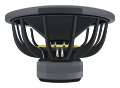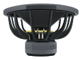
Measure Thiele-Small parameters.
Estimate damping from the impedance peak, then choose added mass or a known sealed test box to estimate compliance and moving mass. Use low-level, consistent measurements.

Impedance measurement
Measurement method
Air & conventions
Read this result with its assumptions.
An isolated resonance, negligible inductance near fs, and low-level measurements are assumed. Both crossing frequencies must be measured at the stated crossing impedance.
Units & assumptionsYour calculations run in this browser. No account needed.
The math, in plain sight.
Measure the driver you will actually install.
Resonance and quality factors
An impedance sweep provides a useful check on a data sheet. Measure complex voltage and current at a low drive level. In an isolated, low-inductance resonance, find the two crossings at the geometric mean of DC resistance and peak impedance.
Added-mass method
Attach a known mass securely and measure the new, lower resonance. This assumes that the added mass does not change suspension compliance.
With fs = 40 Hz, fa = 32 Hz, and an added mass of 20 g, the estimated moving mass is 35.6 g.
Known sealed-box method
Use a rigid, airtight box with a known net volume. The resonance must rise. Changes in air loading and losses are assumed small. Keep driver orientation and temperature consistent, and use effective piston area.
A poorly sealed test box corrupts the result. These relationships assume negligible voice-coil inductance around resonance and a valid measured DC resistance.